
Computer Graphics Raytracing project
Please note - the information on this page is subject to change until the course starts.
General note: In various exercises you will be asked to implement new functionality. In these cases your ray tracer should accept the (syntax of the) example scene files provided. Under no circumstances should your ray tracer be unable to read older scene files (those that do not enable the new functionality), or modify the interpretation of older scene files.
Getting Started: A raytracer framework
In this assignment you will setup the environment for your ray tracer implementation. A note on programming languages: the framework we provide is written in C++, however, you are free to use any other language (but be sure your raytracer works on the lab machines).
Tasks:
- Install the source code of the ray tracer framework. The C++ version includes a Makefile for gcc/MingW (for building on windows):
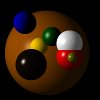
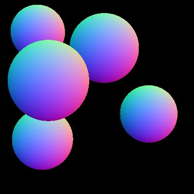
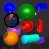
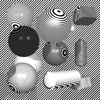
Compile it and test whether it works. Using the supplied example scene
scene01.yamlthe following image should be created: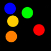
- Look at the source code of the classes and try to understand the program. Of particular importance is the file
triple.hwhich defines mathematic operators on vectors, points, and colors. The actual raytracing algorithm is implemented inscene.cpp. The YAML based scene files are parsed in raytracer.cpp. Look at the included README file for a description of the source files.
1. Raycasting with spheres & Phong illumination
In this assignment your program will produce a first image of a 3D scene using a basic ray tracing algorithm. The intersection calculation together with normal calculation will be the groundwork for the illumination.
- For now your raytracer only needs to support spheres. Each sphere is given by its midpoint, its radius, and its surface parameters.
- A white point-shape light source is given by its position (x,y,z) and color. In the example scene a single white light source is defined.
- The viewpoint is given by its position (x,y,z). To keep things simple the other view parameters are static: the image plane is at z=0 and the viewing direction is along the negative z-axis (you will improve this later).
- The scene description is read from a file.
Tasks:
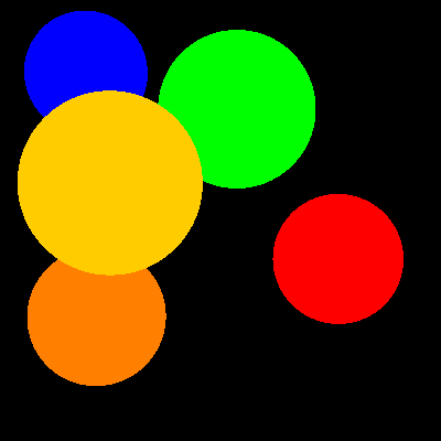
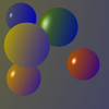
- Implement the intersection calculation for the sphere. Extend the function
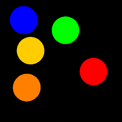
Sphere::intersect()in the filesphere.cpp. The resulting image should be similar to the following image:
- Implement the normal calculation for the sphere. To this end, complete the function
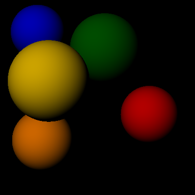
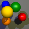
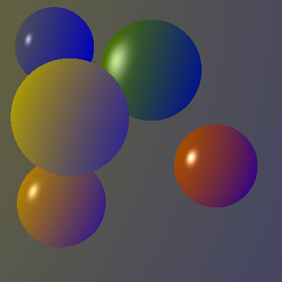
Sphere::intersect()in the filesphere.cpp. Because the normal is not used yet, the resulting image will not change. - Implement the diffuse term of Phong's lighting model to obtain simple shading. Modify the function
Scene::trace(Ray)in the filescene.cpp. This step requires a working normal calculation. The resulting image should be similar to the following image: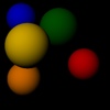
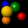
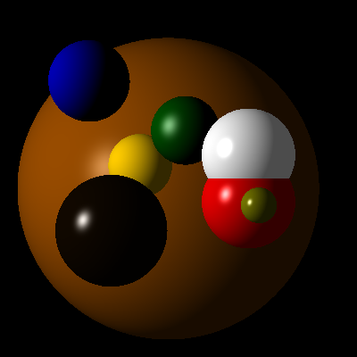
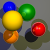
- Extend the lighting calculations with the ambient and specular parts of the Phong model. This should yield the following result:
- Test your implementation using this scene file. This should yield the following result:

2. Normal buffer & z-buffer & additional geometry
In raytracing, Hidden Surface Removal (HSR) is basically included in the technique and you are using (without noticing) a z-buffer-like algorithm in your raytracer. In this assignment you will gain a deeper understanding of this process. In addition you will create a normal buffer.
Tasks:
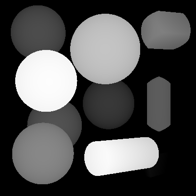
- Adapt your program such that it can also produce a z-buffer image instead of the usual rendering. This should be configurable in the scene file. For this introduce a
RenderModedirective which can be set tozbufferinstead of the defaultphong. Use gray levels to code distances. Make sure you use the whole range of gray levels available to display the image (scale using min, max). An example z-buffer image: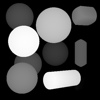
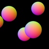
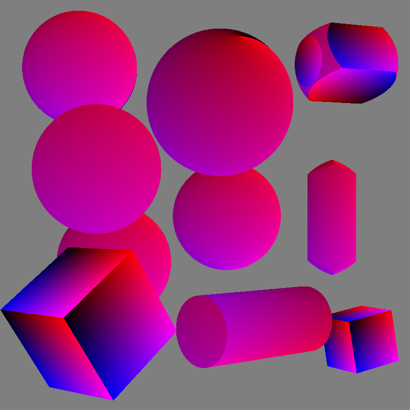
- Adapt your program such that it can also a produce a normal buffer image instead of the normal rendering (again, this should be configurable in the scene file, name it
normal). Map the three components of a normal to the three colors (be sure to map the possible range of the components (-1..1) to the range of the colors). Two example normal buffer images (of two different eye positions, the second is taken from [1000,200,200], and needs an adjustment in scene.cpp to look in the right direction):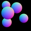
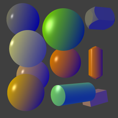
- Implement two(!) geometries from the following list:
- Quad
- Plane
- Cylinder
- Cone
- Triangle
- Torus
- Reading the parameters
- Intersection calculation
- Normal calculation
- (Bonus) Experiment with your own scene descriptions. Even with just spheres you can build some interesting scenes!

Use the following additional(!) scene files to test your implementation:
- Attach:scene01-phong.zip: Explicitly uses phong shading.
- Attach:scene01-zbuffer.zip: Shows z values.
- Attach:scene01-normal.zip: Shows normal buffer.
3. Optical laws
In this assignment you will implement a global lighting simulation. Using recursive ray tracing the interaction of the lights with the objects is determined. The program should be able to handle multiple colored light sources and shadows.
Tasks:
- Extend the lighting calculation in
Raytracer::trace(Ray)such that it produces shadows. First make it configurable whether shadows should be produced (e.g.,Shadows: true). The general approach for producing shadows is to test whether a ray from the light source to the object intersects other objects. Only when this not the case, the light source contributes to the lighting. For the following result a large background sphere is added to the scene (scene01-shadows.yaml).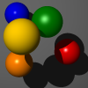
- Now loop over all light sources (if you didn't do that already) and use their color in the calculation. For the following result two different lights were used (scene01-lights-shadows.yaml).
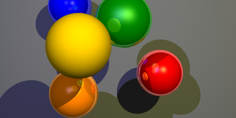
- Implement reflections, by recursively continuing rays in the direction of the reflection vector, treating the found values as light sources. Be sure to only compute the specular reflection for these "light sources" (ambient makes no sense at all, and diffuse reflection is better approximated by NOT taking it into account in this coarse approximation). Example result with a maximum of two reflections (scene01-reflect-lights-shadows.yaml) (if your output looks like this, you might want to have another look at your sphere intersections):


(Bonus) Implement refraction, by recursively continuing rays in the direction of the transmission vector, using the parameters refract and eta, where eta is the index of refraction of the material.
(Bonus) You'll notice that the specular reflections from the scene are not blurred, like the light sources. One way to do something about this is to sample along multiple rays (around the reflection vector) and average the results. Note that for a correct result you should be careful about selecting your vectors and/or the way you average them. Hint: if you take a normal average you should select more rays in those areas where the specular coefficient is high.
(Bonus) Test your implementation using a scene you designed yourself.
4. Anti-aliasing & Extended Camera Model
This assignment starts with anti-aliasing, which will result in better looking images. In addition you will make it easier to move the camera position by implementing an extended camera model.
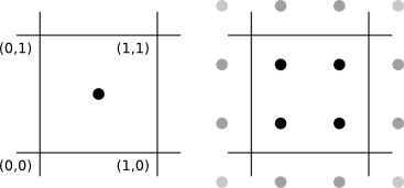
- Implement super-sampling (anti-aliasing), i.e., casting multiple rays through a pixel and averaging the resulting colors. This should give your images a less jagged appearance. Note that you should position the (destinations of the) initial rays symmetrically about the center of the pixel, as in this figure (for 1x1 and 2x2 super sampling):
- Again, make sure this is configurable in the scene file. The default should be to have no super sampling (or, equivalently, super sampling with a factor of 1). An example of 4x4 super-sampling (scene01-ss.yaml):
- Implement an extended camera model such that other image resolutions are possible and producing images becomes more flexible. You should keep support for the Eye parameter for backwards compatibility, but allow the specification of a Camera object (instead of the Eye parameter). You should support an eye position, a reference point (center) as in OpenGL, an up vector and a viewSize (the size of a pixel is determined by the length of the up vector). An example of what this should look like (scene01-camera-ss-reflect-lights-shadows.yaml and scene01-zoom-ss-reflect-lights-shadows.yaml):


- For more information on constructing a view, see A Simple Viewing Geometry and chapter 7 of your book. And keep in mind that the length of the up vector determines both the "vertical" and the "horizontal" dimensions of a pixel (you can implement additional functionality to allow for stretched views if you want).


(Bonus) Implement apertureRadius and apertureSamples parameters for your camera object and use them to simulate depth of field by taking apertureSamples positions (uniformly) within apertureRadius of the eye (note that this disc should be formed using the up and right vectors). This can look like the figure below, using Vogel's model with n in [0,apertureSamples), r=c*sqrt(n), th=n*goldenAngle and c=apertureRadius/(up.length()*sqrt(apertureSamples)) to sample the aperture (scene01-dof-ss-reflect-lights-shadows.yaml):

(Bonus) As you may have noticed this tends to create visible "rings", instead of blurring the out-of-focus objects. To combat this, you should make sure that in the computation of the angle n is offset by the index of the (sub)pixel in the image (so if the image is 10x10 with no supersampling the last index is 99), and similarly that in the computation of the radius n is offset by fmod(pixel_index*golden_ratio,1.0) (or similar). This works because the golden ratio (and similarly the golden angle) is irrational and very good at producing a sequence of numbers that "looks random" (but more evenly distributed). The effect can be seen in these images (the left image uses the exact same scene file as before, the right image has been made using apertureSamples=16 instead of 4):


(Bonus) Implement additional supersampling types (see Wikipedia for general information).
(Bonus) Add an optional velocity attribute to objects (default is [0 0 0]) and an exposureTime attribute to Camera (default is 0). Implement motion blur, assuming that the exposure is between -exposureTime/2 and exposureTime/2, and that at time t an object is at position+t*velocity. You should probably also add another attribute exposureSamples to control the number of samples to take, and feel free to vary as much as you like on the theme (you can also let the camera move for example, or allow for more than just linear motion).
5. Texture mapping and alternative illumination models
Tasks:
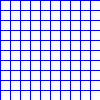
- Implement texture mapping. With textures it becomes possible to vary the lighting parameters on the surface of objects. For this a mapping from the points of the surface to texture-coordinates is needed. You might want to make a new pure virtual function in Object (and give it a non-trivial implementation in at least Sphere) for computing texture coordinates so that it only has to be done for objects which actually need it. See Links and References for links to example textures to use and section 11.2 (2D texture mapping) of your book for how to compute the texture coordinates. For reading the textures you can use the following line:
Image *texture = new Image("bluegrid.png");, and access the pixel data:texture->colorAt(float x, float y), where x and y are between 0 and 1.
- Also implement rotation of (at least) spheres (if you haven't already). In this case you are NOT required to exactly follow the syntax given here, but you are required to implement something that gives the same degrees of freedom. In the example given here the vector defined by radius[0]*radius[1].normalized() is mapped to (0,0,1) through the simplest possible rotation and then the whole sphere is rotated by
angledegrees around the z-axis (note that this corresponds to subtracting the angle in radians from the angle gotten by the arctan). This should look like this (scene01-texture-ss-reflect-lights-shadows.yaml):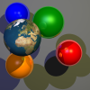
- In particular for illustration purposes alternative illumination models have been developed, which are rather easy to implement in your raytracer. In this assignment you will implement one of these models.
Your task is to implement the illumination model by Gooch et al. Be aware of the following:
- The formula for the lighting calculation in the original paper is not correct. Use this one: I = kCool *(1 - dot(N,L))/2 + kWarm * (1 + dot(N,L))/2 (note that for this formula it is not necessary that dot(N,L)<0).
- The variable
kdin the paper can be set tolights[i]->color*material->color*material->kd. - Extend the scene description for the new parameters
b,y,alphaandbeta(reminder: your ray tracer should still accept files that do not set these parameters). - The Gooch model should not replace the Phong model, instead which model will be used should be configurable.
- Gooch should not use ambient lighting, but it can use the same kind of highlights as in Phong shading (the specular component of Phong shading).
- When using Gooch shading you may ignore shadows and/or reflections, but you are not required to (and you might be able to get some interesting effects by not ignoring them).


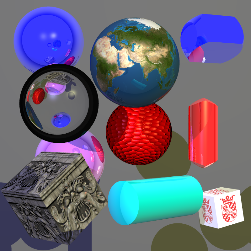
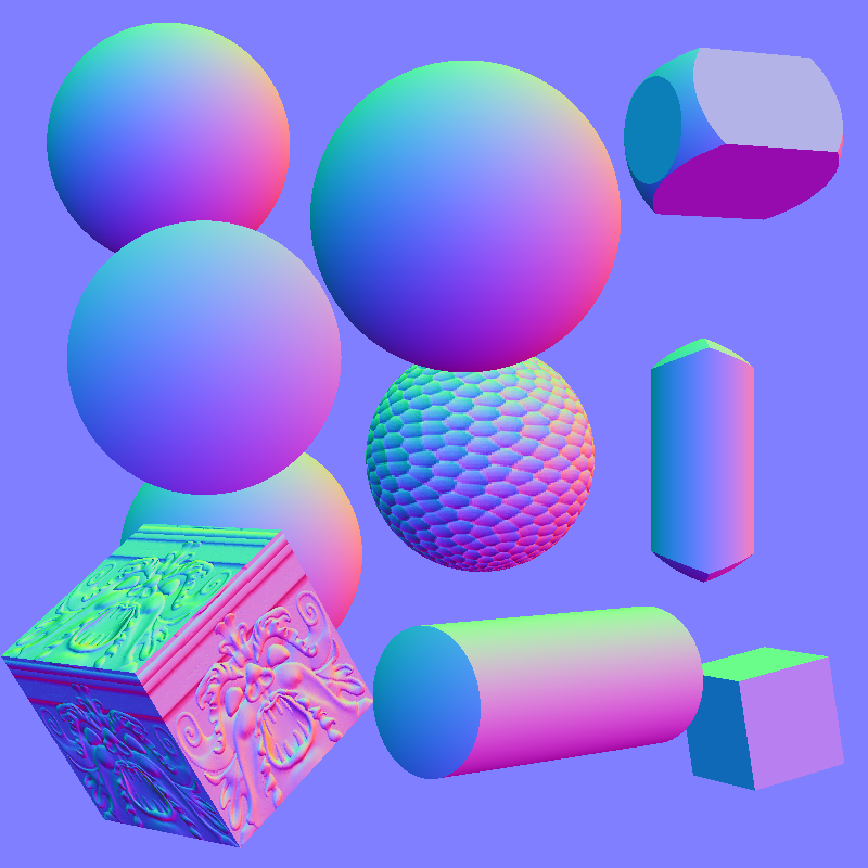
For testing your texture mapping code you may want to use the following files (for the result, see the presentation):
(Bonus) Implement bump-mapping. The results could be something similar to the following (texture coordinates, texture mapping, bump mapping, normal buffer):

(Bonus) For the Gooch shading: add a black line to the silhouettes of your objects. This should create a really nice effect (as was seen in the tutorial presentation)
6. More geometries and 3D mesh files
- Implement an additional geometry type from the above or following list. Make sure however, you have implemented at least a triangle.
- Quad
- Planes (determined by a point and a normal)
- Polygon (determined by corner points)
- Cylinder, Cone, parabolic surfaces
- Torus (can have 4 intersections points)
- Blobs
- Free-form surfaces
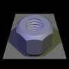
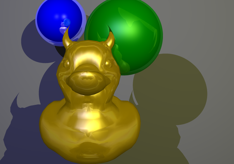
- Implement 3D mesh objects (read from a file). Use the code (
glm.candglm.h) you used in the OpenGL Project (just remove the drawing code, this way you do not have to link to OpenGL). You can use the same models, but be aware that producing a raytraced image of a model with many triangles can take a long time. For example, the following image of an evil golden rubber duck (with 3712 triangles) took almost nine hours to generate on a reasonably fast machine (with 3x3 super-sampling, relatively unoptimized code).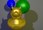
- Include your coolest result(s) (either from the Raytracer or the OpenGL project) in the archive that you hand in. These results will be used for the gallery page? of this year. You can use images (renders & screenshots), but videos are allowed too :) Please don't hide these files too deep in your archive, so that I can easily spot them.
- (Bonus) Implement constructive solid geometry (CSG). Here is an example of a rendering with cylinders and CSG objects:
Or a more complex CSG shape:

(Bonus) Raytracer extensions
The possibilities for extending your raytracer are endless. For inspiration, take a look at the following list (for more information check your Computer Graphics book or the internet):
- Exposure time (motion blur)
- Soft shadows
- Depth of focus
- Lens flare
- Optimizations:
- Reduction of the number of rays:
- Adaptive super-sampling and sub-sampling.
- Insignificance test: when the weight of a ray becomes smaller than a certain value the contribution of the ray is negligibly small and the recursion can be stopped.
- Reducing the number of objects to do intersection tests on.
- Faster rendering for primary rays: which object can be seen in which pixel can be determined by a conventional renderer (z-buffer, scanline).
- Bounding volumes
- Space-Subdivision methods
- Distributed ray tracing
- Reduction of the number of rays:
- Parallelization. Raytracing is inherently parallel and it is fairly easy to parallelize, in particular on today's multi-core PCs. Techniques to consider include:
- Native threads
- Intel Threading Building Blocks
- Smart use of OpenMP. Not just #pragma openmp parallel for
- NVIDIA's CUDA (using GPU for general purpose programming)
- OpenCL (cross-platform - including GPU - parallel programming)
- Non-Photorealistic Rendering (NPR):
- Implement Leister's Hatching method:
- Implement Luft's "Image Enhancement by Unsharp Masking the Depth Buffer".
- Obtain inspiration for your own ideas here
